Automatic Labeling Settings
In the Project Environment dialog, Document Production > Automatic Labeling Settings contains settings for automatic labeling of drawing views. An "Automatic Labeling Settings" configuration selects a particular labeling style and defines to which objects to apply that style. Each project must have at least one such configuration object that designers can select when starting to generate labels, as described in Automatic Labeling.
Defining Automatic Labeling Settings
Create an "Automatic Labeling Settings" configuration object to provide default settings for automatic labeling. You can create the configuration in the library database, and then approve it for use in the relevant projects.
Prerequisites
-
The Label Definitions to use in automatic labeling. See Label Definitions.
-
The Labeling Style to use in automatic labeling. A Labeling Style defines the default visual properties of the labels, lists the Label Definitions that receive those visual properties, and allow the default properties to replaced by Label Definition specific values. For example, all the labels might use the default text height, but text color would depend on each Label Definition. See Labeling Styles.
Do the following:
-
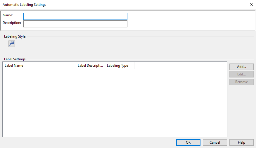
In the Project Environment dialog, browse to [library] > Document Production > Automatic Labeling Settings and select New > Automatic Labeling Settings. The Automatic Labeling Settings dialog opens.
-
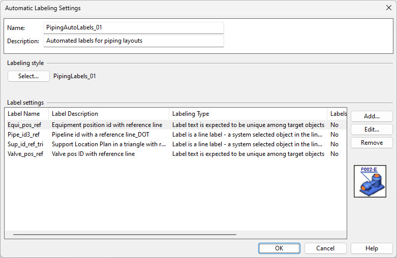
Enter a name and description for the settings.
-
In the Labeling style section, click Select. The Select Labeling Style dialog opens, listing the available styles. (If you are creating the settings in the library database, it only lists styles that are stored in the library.)
-
Select the labeling style to use and click OK.
-
In the Label settings section, click Add. The Select Label Definitions to Add dialog opens, listing the label definitions of the selected labeling style.
-
Hold down Ctrl or Shift and select the label definitions to use, and then click OK. The selected label definitions are listed in the Label settings pane.
-
Define the settings for each label definition:
-
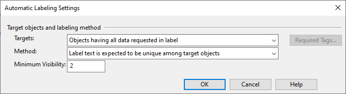
Select a label definition from the list and click Edit. The Automatic Labeling Settings dialog opens.
-
-
Targets – Each label definition has a data request (a list of tags) that it uses to retrieve information from the target objects. The retrieved information is formatted as specified in the label definition and forwarded to a 2D symbol that then draws the text in the label.
This setting allows you to specify which of the tags an object should have to be labeled.
 Show/hide details
-
Objects having all data requested in label – Inserts a label to target objects that have all the tags that are defined in the label definition's data request.
-
Objects having all required tags – Inserts a label to target objects that have all the tags that you select with Required Tags but not necessarily all the tags that are defined in the data request.
For example, if ".k6" (Object's insulation specification) is in the data request but is NOT a required tag, the same label definition can add a label to both insulated and non-insulated pipes, and for insulated pipes the label can also show the name of the specification.
-
Objects having at least one of required tags – Inserts a label to target objects that have at least one of the tags you select with Required Tags.
For example, if "vpo" and "ipo" are among the required tags, the same label definition can add a position ID label to both valves and instruments.
-
-
Method – This setting allows you to specify what should happen when multiple objects use the same label definition and might have the same value in the label.
Show/hide details
-
Label text is expected to be unique among target objects – Select this option if the label shows content that is specific to the target object.
For example, if the label shows the object's position ID, every object is expected to have a different position ID. If, however, several objects would have the same label, only one of them is labeled.
-
Label text is non-unique - all target objects will be labeled – Select this option if the same label can be added to many target objects.
For example, if the label shows the object's part number and you want all the parts to be labeled even if they have the same part numbers.
-
Label is a line label - a system selected object in the line will be labeled – Select this option to allow the program to scan the target objects that have the same label text and insert the label to the one that best shows the label.
Typically, you would use this to show a single label for objects that belong to a line or a structural unit.
-
Label is a spool label – Select this option to allow the program to scan the objects in a spool group and insert the label to the object that best shows the label. Because different objects in a spool group might generate a different label text, the text that is shown may depend on the chosen object.
-
Label at start or end of line – Select this option to insert a label to the start of the first spool and the end of the last spool, for each pipeline in the view.
For the label to be added, the pipeline must be visible near the point to which the label's reference line is drawn. If vertical spools are stacked on top of each other, in a top view the labels are visible also when the spool is hidden behind the spools above it.
If the pipeline only consists of one spool, then only one label is added, either to the start or the end of the spool.
-
-
Minimum Visibility – Specifies that automatic labeling should only insert labels for objects with a visible area on paper larger than the specified millimeter value. Set the value to 0 to allow part numbers to be added to hidden objects, such as hatches behind a duct in a duct spool drawing.
-
Place labels to side areas – Select this option to position the labels along the sides of the drawing.
-
Use 45 degree leader lines – Select this option to place the leader lines at a 45-degree angle. This can improve readability, especially in drawings where axis-aligned leader lines may overlap with lines in the drawing or within the drawing sheet.
-
-
Click OK.
-
-
When all the settings are defined, click OK. The settings are saved locally.
-
In the Project Environment dialog, check in the configuration object to make it available to others.